


Hight TG / Aluminum Electronic PCB Assembly
Product Description
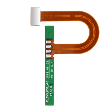
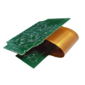
How to assemble a flexible PCB?
FPC is also called flexible circuit board. The PCBA assembly and soldering process of FPC is very different from the assembly of rigid circuit boards. Because the FPC board is not rigid enough and soft, it cannot be fixed and transmitted without using a dedicated carrier board. Basic SMT processes such as printing, placement, and furnace cannot be completed.
one. FPC pretreatment
The FPC board is relatively soft, and it is generally not vacuum-packed when it leaves the factory. It is easy to absorb moisture in the air during transportation and storage. It needs to be pre-baked before SMT is put into line to force the moisture out slowly. Otherwise, under the high temperature impact of reflow soldering, the moisture absorbed by the FPC will quickly vaporize and become water vapor to protrude from the FPC, which will easily cause defects such as FPC delamination and blistering.
The pre-baking conditions are generally at a temperature of 80-100°C and a time of 4-8 hours. Under special circumstances, the temperature can be adjusted to above 125°C, but the baking time needs to be shortened accordingly. Before baking, be sure to make a small sample test to determine whether the FPC can withstand the set baking temperature, or consult the FPC manufacturer for suitable baking conditions. When baking, FPC should not be stacked too much. 10-20PNL is more suitable. Some FPC manufacturers will put a piece of paper between each PNL for isolation. It is necessary to confirm whether this piece of paper for isolation can withstand the set baking. Temperature, if it is not necessary to remove the release paper, then bake it. The baked FPC should have no obvious discoloration, deformation, warping and other defects, and it can be put into line only after being qualified by IPQC.

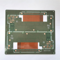
According to the CAD file of the circuit board, read the hole positioning data of the FPC to manufacture the high-precision FPC positioning template and the special carrier board. match. Many FPCs are not of the same thickness because they want to protect part of the circuit or for design reasons. Some places are thicker, some places are thinner, and some have reinforced metal plates. Therefore, the junction of the carrier board and the FPC needs to be The actual situation is to process, polish, and dig grooves, and the function is to ensure that the FPC is flat during printing and placement. The material of the carrier board is required to be light and thin, high strength, low heat absorption, fast heat dissipation, and small warpage deformation after multiple thermal shocks. Commonly used carrier materials include synthetic stone, aluminum plate, silica gel plate, special high-temperature resistant magnetized steel plate, etc.

Here we take a common carrier board as an example to elaborate on the SMT key points of FPC. When using a silicone plate or a magnetic fixture, the fixing of the FPC is much more convenient and does not need to use tape. The key points of the process of printing, patching, soldering, etc. are the same.
1. Fixing of FPC:
Before SMT, the FPC needs to be accurately fixed on the carrier board. It is especially important to note that the shorter the storage time between printing, mounting and soldering after the FPC is fixed on the carrier board, the better. There are two kinds of carrier boards with positioning pins and without positioning pins. The carrier board without locating pins needs to be used with the locating template with locating pins. Put the carrier board on the locating pins of the template first, so that the locating pins are exposed through the locating holes on the carrier board, and put the FPC piece by piece on it. The exposed positioning pins are then fixed with tape, and then the carrier board is separated from the FPC positioning template for printing, patching and welding. There are several spring positioning pins about 1.5mm in length on the carrier board with positioning pins. The FPC can be directly put on the spring positioning pins of the carrier board one by one, and then fixed with tape. In the printing process, the spring positioning pin can be completely pressed into the carrier plate by the steel mesh without affecting the printing effect.
Method one (fixed with single-sided tape): Use thin, high-temperature single-sided tape to fix the four sides of the FPC on the carrier board to prevent the FPC from shifting and warping. The viscosity of the tape should be moderate, and it must be easy to peel off after reflow. There is no residual glue on the surface. If you use an automatic tape machine, you can quickly cut tapes of the same length, which can significantly improve efficiency, save costs, and avoid waste.
Method two (fixed with double-sided tape): first use high-temperature resistant double-sided tape to stick to the carrier board, the effect is the same as the silicone plate, and then paste the FPC to the carrier board, pay special attention to the viscosity of the tape not to be too high, otherwise it will peel off after reflow soldering It is easy to cause the FPC to tear. After repeated heating, the viscosity of the double-sided tape will gradually decrease. If the viscosity is too low to reliably fix the FPC, it must be replaced immediately. This station is the key station to prevent the FPC from getting dirty, and it is necessary to wear finger cots to work. Before the carrier board is reused, it needs to be properly cleaned. It can be wiped with a non-woven cloth dipped in detergent, or an anti-static sticky roller can be used to remove surface dust, tin beads and other foreign objects. Don't use too much force when picking and placing FPC. FPC is fragile and prone to creases and breaks.

FPC does not have very special requirements for the composition of solder paste. The size and metal content of the solder ball particles are subject to whether there are fine-pitch ICs on the FPC. However, FPC has higher requirements for the printing performance of solder paste, and the solder paste should have excellent Thixotropy, the solder paste should be easy to print and release and firmly adhere to the surface of the FPC, and there will be no defects such as poor release, blocking the leakage of the stencil or collapsing after printing.
Because the carrier board is loaded with FPC, there is a high temperature resistant tape for positioning on the FPC, which makes the plane inconsistent. Therefore, the printed surface of the FPC cannot be as flat as the PCB and the thickness and hardness are the same. -90 degree polyurethane type scraper. The solder paste printer is best equipped with an optical positioning system, otherwise it will have a greater impact on the printing quality. Although the FPC is fixed on the carrier board, there will always be some tiny gaps between the FPC and the carrier board. This is due to the rigidity of the PCB. The biggest difference between the board, so the setting of equipment parameters will also have a greater impact on the printing effect.
The printing station is also a key station to prevent the FPC from being dirty. It is necessary to wear finger cots to work. At the same time, keep the station clean and wipe the steel mesh frequently to prevent the solder paste from contaminating the FPC's gold fingers and gold-plated buttons.
3. FPC patch:
According to the characteristics of the product, the number of components and the placement efficiency, medium and high-speed placement machines can be used for placement. Since there is an optical MARK mark for positioning on each FPC, there is not much difference between SMD mounting on FPC and mounting on PCB. It should be noted that although the FPC is fixed on the carrier board, its surface cannot be as flat as a PCB hard board. There will definitely be a partial gap between the FPC and the carrier board. Therefore, the suction nozzle drop height, blowing pressure, etc. It needs to be set accurately, and the moving speed of the suction nozzle needs to be reduced. At the same time, FPCs are mostly connected boards, and the yield of FPCs is relatively low. Therefore, it is normal for the whole PNL to contain some bad PCS. This requires the placement machine to have the BAD MARK recognition function, otherwise, in the production of this type of non-integral When PNL is a good board, the production efficiency will be greatly reduced.
4. Reflow soldering of FPC:
The forced hot air convection infrared reflow oven should be used, so that the temperature on the FPC can be changed more uniformly, and the occurrence of poor soldering can be reduced. If you use a single-sided tape, because you can only fix the four sides of the FPC, the middle part is deformed under hot air, the pad is easy to form an inclination, and the molten tin (liquid tin at high temperature) will flow, resulting in empty welding, continuous welding, Tin beads make the process defect rate higher.
1) Temperature curve test method:
Due to the different heat absorption properties of the carrier board and the different types of components on the FPC, the temperature rises at different speeds after being heated during the reflow soldering process, and the heat absorbed is also different. Therefore, carefully set the temperature curve of the reflow oven to improve the quality of soldering. Great influence. A more reliable method is to place two FPC-equipped carrier boards before and after the test board according to the carrier board interval during actual production. At the same time, mount components on the FPC of the test carrier board, and use high-temperature solder wire to test the temperature. The probe is welded on the test point, and the probe wire is fixed on the carrier board with a high-temperature adhesive tape. Note that the high temperature resistant tape cannot cover the test point. The test points should be selected near the solder joints and QFP pins on each side of the carrier board, so that the test results can better reflect the real situation.
2) Setting of temperature curve:
In the furnace temperature debugging, because the FPC's temperature uniformity is not good, it is best to use the temperature curve method of heating/heat preservation/reflow, so that the parameters of each temperature zone are easier to control, and the FPC and components are affected by thermal shock. Some. According to experience, it is best to adjust the furnace temperature to the lower limit of the solder paste technical requirements. The wind speed of the reflow furnace is generally the lowest wind speed that the furnace can use. The chain of the reflow furnace should be stable and free of jitter.
5. FPC inspection, testing and sub-boarding:
Since the carrier plate absorbs heat in the furnace, especially the aluminum carrier plate, the temperature is higher when it is out of the furnace, so it is best to add a forced cooling fan at the furnace outlet to help cool down quickly. At the same time, operators need to wear heat-insulating gloves to avoid being burned by the high-temperature carrier. When taking out the soldered FPC from the carrier board, the force should be even, and brute force should not be used to prevent the FPC from being torn or creases.
The removed FPC is visually inspected under a magnifying glass of more than 5 times, focusing on the inspection of residual glue on the surface, discoloration, golden finger tin, tin bead, IC pin empty welding, continuous welding and other problems. Since the surface of the FPC cannot be very smooth, which makes the AOI misjudgment rate high, the FPC is generally not suitable for AOI inspection. However, by using special test fixtures, the FPC can complete the ICT and FCT tests.
Since FPC is mostly connected to the board, it may be necessary to split the board before testing the ICT and FCT. Although the splitting operation can also be completed using tools such as blades and scissors, the operation efficiency and quality of the operation are low, and the scrap rate is high. If it is mass production of special-shaped FPC, it is recommended to make a special FPC stamping die for stamping and splitting, which can greatly improve the work efficiency. At the same time, the edges of the punched FPC are neat and beautiful, and the internal stress generated by stamping and cutting is very low. Can effectively avoid solder joint cracking.
In the assembly and welding process of PCBA flexible electronics, the precise positioning and fixing of FPC are the key points, and the key to fixing is to make a suitable carrier board. Followed by FPC pre-baking, printing, placement and reflow soldering. Obviously, the difficulty of FPC SMT process is much higher than that of PCB rigid board, so it is necessary to set process parameters accurately. At the same time, strict production process management is also important. It is necessary to ensure that operators strictly implement every regulation on SOP and follow the line. Engineers and IPQC should strengthen inspections, find abnormal conditions in the production line in time, analyze the causes and take necessary measures to control the defect rate of the FPC SMT production line within dozens of PPM.
In the PCBA production process, a lot of machinery and equipment are needed to assemble a board. Often the quality level of a factory's machinery and equipment directly determines the manufacturing capacity.
The basic equipment required for PCBA production includes solder paste printer, placement machine, reflow soldering, AOI detector, component trimming machine, wave soldering, tin furnace, washing machine, ICT test fixture, FCT test fixture, For aging test racks, PCBA processing plants of different sizes have different equipment.
Product Categories : High Frequency Board > Multi-wiring Printed Board